




Inside every Variable Frequency Drive, there is a set of high-speed electronic switches called IGBTs.
IGBT stands for Insulated Gate Bipolar Transistor. These components are the core of the VFD inverter stage. They directly control motor speed and torque.
Understanding IGBTs helps engineers maintain drives, diagnose faults faster, and select higher-quality equipment.

What Is an IGBT?
An IGBT is a three-terminal semiconductor switch. It combines the best features of the two transistor types. It switches on and off very quickly — thousands of times per second — under high voltage and current.
Inside a VFD, six IGBTs are arranged in a three-phase inverter bridge (two per output phase). The three terminals are:
- Gate (G) — receives the switching signal from the drive control board.
- Collector (C) — connects to the positive or negative DC bus rail.
- Emitter (E) — connects to the motor output terminal.

How Pulse Width Modulation (PWM) Controls Motor Speed
After the AC mains supply is converted to DC, the DC bus voltage is typically 530 to 680 V. The six IGBTs chop this DC voltage into a series of precisely timed pulses. This process is called Pulse Width Modulation, or PWM.
The control board adjusts the on/off timing of each IGBT pair thousands of times per second. The motor windings act as a natural filter due to their inductance. The pulsed voltage averages into a smooth current at exactly the frequency and voltage required.
The MC9001 allows users to adjust PWM carrier frequency (parameter F0.15) between 2 kHz and 16 kHz. Higher frequency produces smoother motor operation but increases heat in the drive. Lower frequency reduces drive temperature but may increase motor noise slightly.
| 📌 Note: For most industrial applications, a carrier frequency of 4–6 kHz offers a good balance between motor smoothness and drive temperature. |
They also switch more slowly, which increases heat and reduces drive efficiency. MINGCH sources premium IGBT modules for every MC9001 drive. Each unit undergoes a full-load burn-in test at the factory before shipment. This ensures that only fully verified drives reach the customer.
For wholesalers and trading companies, this means fewer warranty returns and stronger client satisfaction.
How to Test an IGBT Module with a Multimeter
If a drive trips on an OC (overcurrent) fault immediately at startup, a shorted IGBT is a likely cause. Follow these steps to test safely:
Step 1 — Power Off and Discharge:
- Switch off the mains power and wait at least 10 minutes.
- Measure DC voltage across bus terminals P+ and N− using a multimeter.
- Do not open the drive enclosure until the reading drops below 36 V.
Step 2 — Diode Mode Test:
- Set the multimeter to diode test mode.
- Place the red probe on the Collector (C) and the black probe on the Emitter (E). A healthy IGBT reads open circuit (OL) in this direction.
- Reverse the probes. A healthy device shows 0.3 to 0.7 V — the forward voltage of its built-in diode.
- A reading of zero in both directions indicates a shorted IGBT. The module must be replaced.
Step 3 — Gate Function Test:
- Touch a 9V battery briefly between Gate (G) and Emitter (E), positive terminal to Gate. Measure collector-to-emitter resistance. The resistance will go down, showing the IGBT is now ON.
- Remove the battery. The resistance should return to high, signaling that the device is now OFF.
- A device that does not respond to gate voltage is faulty and must be replaced.
Other Possible Causes of Overcurrent Faults
Not every OC fault means a failed IGBT. Always check these items first. Motor insulation resistance should exceed 1 MΩ at 500V (test with a Megger instrument).
The motor cable should be correctly shielded and within the recommended length. Acceleration and deceleration ramp times may be set too short for the load. Mechanical issues, such as a seized bearing, can cause repeated OC faults.
The MC9001 stores the last 10 fault events with operating data (frequency, current, voltage, temperature). Review this fault log before replacing any components.
Why You Should Replace Faulty IGBTs
The IGBT in a VFD is like the heart of the drive. It switches electricity thousands of times every second and controls motor speed and torque. Over time, IGBTs can wear out or fail. If an IGBT is damaged, the VFD may stop working, make the motor run incorrectly, or even damage the motor.
Replacing a faulty IGBT quickly keeps the VFD running safely, restores smooth motor control, and prevents more serious problems. High-quality replacements also reduce the chance of repeated faults and make the system more reliable.
MINGCH MC9001: Reliable VFD Inverters
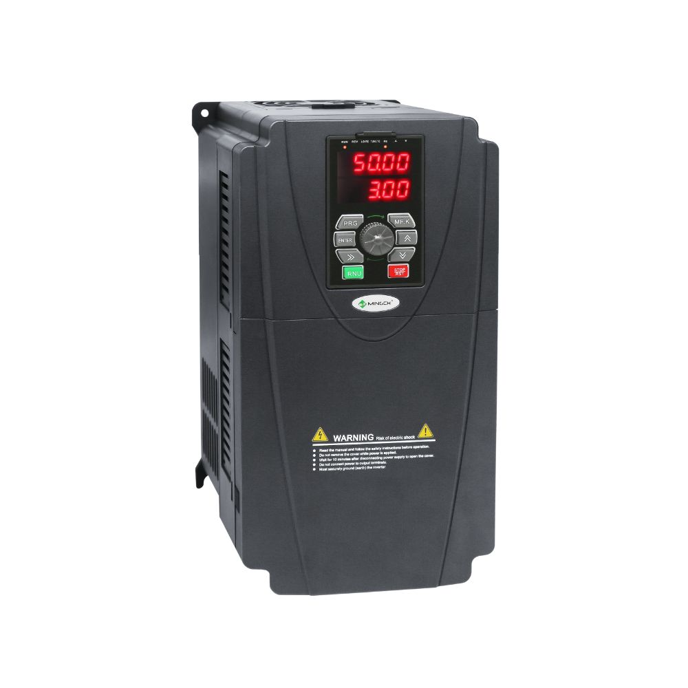
For industrial use, MINGCH offers high-quality VFD inverters with strong and durable IGBT modules. The MC9001 series is designed for precise motor control, stable operation, and safety. It works well in many applications, including fans, pumps, packaging machines, and automated production lines.
The MC9001 supports different input voltages, including single-phase 220V, three-phase 220V, and three-phase 380V. It can deliver frequencies from 0 to 500 Hz, and higher if customized. The drive also has built-in protection against overvoltage, undervoltage, overcurrent, overload, overheating, phase loss, and short circuits.
MINGCH tests every drive at the factory to ensure quality. They also provide technical support, spare parts, and guidance for replacing IGBT modules safely. This makes installation and maintenance easier for repairers, system integrators, and wholesalers.
You can see the full range of MINGCH VFD products here: MINGCH Product Catalog.
Discover MINGCH Manufacturing Excellence
Step inside our factory to see how high-quality voltage regulators and inverters are engineered for precision and durability.
Explore Our FactoryFrequently Asked Questions (FAQs)
What is an IGBT in a VFD?
An IGBT is a fast-switching transistor inside a VFD inverter. It converts DC into controlled AC, regulating motor speed, torque, and direction for precise operation.
How does pulse width modulation (PWM) work in a VFD?
PWM switches DC voltage on and off via IGBTs. Motor inductance smooths these pulses into near-sinusoidal AC, controlling voltage and frequency for accurate speed and torque.
How can I check an IGBT in a VFD?
Power off the drive, discharge the DC bus, and use a multimeter in diode mode. Check the collector-emitter and gate-emitter response. Faulty readings indicate the IGBT must be replaced.
What causes overcurrent faults in a VFD?
OC faults may result from shorted IGBTs, motor insulation issues, long or improperly shielded cables, mechanical problems, or too-fast acceleration/deceleration ramps.
Why is IGBT quality important?
High-quality IGBTs handle repeated high-speed switching and voltage stress, ensuring reliable VFD operation. Low-quality devices fail under inrush or braking, reducing drive life.
Can I integrate a VFD with a PLC?
Yes. Hardwired digital/analog control suits single drives, while Modbus RTU allows one PLC to manage multiple VFDs. Proper wiring and settings protect IGBTs.
What is a typical PWM carrier frequency for industrial applications?
A PWM frequency of 4–6 kHz balances smooth motor operation and drive temperature. Higher frequencies smooth motion but increase heat; lower frequencies reduce heat but slightly increase motor noise.


