




Precise motor speed control starts with one solid connection. This is the link between your Variable Frequency Drive (VFD) and your Programmable Logic Controller (PLC).
Whether you are automating an elevator, a packaging line, or a printing machine, getting the VFD and PLC to communicate correctly is the foundation of the entire system.
This guide walks you through the physical wiring and communication setup for the MINGCH MC9001 frequency inverter. Both hardwired control and Modbus RTU methods are covered step-by-step.
Understanding the VFD–PLC Relationship
A PLC is the brain of any automated system. It reads inputs from sensors and sends commands to output devices.
A VFD is the motor controller. It receives those commands and adjusts motor speed, torque, and direction accordingly.
When these two devices are connected correctly, the PLC gains full control over the motor—with no manual intervention required.
The MINGCH MC9001 supports two primary integration methods:
- Hardwired control — uses physical signal wires for direct, reliable control over short distances.
- Modbus RTU over RS-485 — uses serial communication to control multiple drives from one PLC on a single cable.
Choose hardwired control for simple, single-drive setups. Choose Modbus when managing several drives across a larger system.
Method 1 — Hardwired Control (Digital and Analog Signals)
This is the most straightforward way to connect a VFD and PLC. It is best suited for cable runs under 30 meters.
- Starting and Stopping the Motor
Connect the PLC digital output (DO) to terminal S1 on the MC9001 for forward rotation. Use terminal S2 for reverse. Connect the common wire to the COM terminal.
Then set parameter F0.02 = 1 on the drive to activate external terminal control.
- Controlling Motor Speed (Analog Signal)
Connect the PLC analog output — either 0–10V or 4–20mA — to terminals AI1 and GND on the MC9001.
Set F0.03 = 2 to use the analog input as the speed reference. Adjust F4.00 and F4.01 to set the target frequency range (for example, 0 to 50 Hz).
- Multi-Speed Preset (Optional)
You can assign up to 16 preset speeds using PLC digital outputs on terminals S3 to S6. Configure target frequencies in parameter group F5.00 to F5.15.
This is widely used in packaging lines where the same motor runs at different speeds for different product sizes.
- Fault Detection Output
Wire the MC9001 relay output (terminals RA–RC) back to a PLC digital input. Set E0.00 = 1 so the relay activates when a fault occurs. The PLC can then trigger an alarm or initiate a controlled system shutdown.
| ⚠️ Wiring Tip: Always route power cables and control signal cables in separate conduits. This prevents electromagnetic interference and improves signal reliability. |
Method 2 — Modbus RTU over RS-485
Modbus RTU is a serial communication protocol that allows one PLC to control multiple VFDs over a single pair of wires. It is the preferred method for large systems such as multi-pump stations, multi-axis conveyors, or complex elevator installations.
Physical Wiring
Connect the PLC RS-485 port (A+ and B−) to the MC9001 RS-485 terminals. Use shielded twisted-pair cable and ground the shield at one end only. Place a 120-ohm termination resistor across A and B at the last drive on the cable run.
MC9001 Parameter Setup for Modbus
| Parameter | Setting / Value | Purpose |
| F0.02 | 2 | Activates communication control mode |
| F8.00 | 1–247 (unique per drive) | Sets the Modbus device address |
| F8.01 | 9600 (recommended default) | Sets the communication baud rate |
| F8.02 | 8-N-1 | Sets data format for standard Modbus RTU |
Key Modbus Control Registers
| Parameter | Setting / Value | Purpose |
| Register 0x2000 | Write 0x0001 | Start the drive |
| Register 0x2000 | Write 0x0005 | Stop the drive |
| Register 0x2001 | Monitor the current output current | Set output speed |
| Register 0x3000 | Read | Monitor current output frequency |
| Register 0x3005 | Read | Monitor the current output |
Most major PLC brands — including Siemens, Mitsubishi, Delta, and Omron — include pre-built Modbus function blocks in their standard programming libraries. Once the parameters above are set, integration is fast and reliable.

Pre-Power Safety Checklist
Before switching on the system, verify the following:
1. Separate cable routing
Power cables and control signal cables must run in separate conduits.
2. Shield grounding
Ground the cable shield at the drive end only — never at both ends.
3. Motor cable length
Keep motor cables under 50 meters. Add an output reactor for longer runs.
4. Parameter confirmation
Confirm that F0.02 and F0.03 match your chosen control method before power-up.
5. DC bus discharge
After switching off the main power, wait at least 10 seconds before opening the drive enclosure. The internal capacitors need time to discharge safely.
Why System Integrators Choose MINGCH
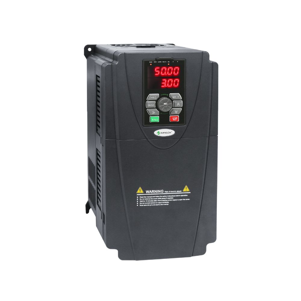
MINGCH manufactures the MC9001 entirely at its own 10,000 m² factory in Zhejiang, China. Every drive is produced and tested in-house — from IGBT sourcing through to full-load burn-in testing before shipment.
Every MC9001 ships with complete wiring diagrams, parameter sheets, and Modbus register maps. For complex multi-drive projects, MINGCH’s engineering team can provide pre-configured parameter files tailored to your specific PLC brand and application.
Direct engineer-to-engineer support is available via WhatsApp. It reduces commissioning time. It resolves technical questions without long delays.
| 🔗 Ready to start your integration project? Visit www.mingchele.com to explore the MC9001 series, download technical documentation, or request a consultation with the MINGCH engineering team. |
Discover MINGCH Manufacturing Excellence
Step inside our factory to see how high-quality voltage regulators and inverters are engineered for precision and durability.
Explore Our FactoryConclusion
Connecting a VFD to a PLC does not have to be complicated. With the right wiring method, the correct parameter settings, and a drive designed for easy integration, you can achieve precise motor control with confidence.
The MINGCH MC9001 gives system integrators two flexible paths — hardwired or Modbus — to suit any application and any scale. And with full technical documentation and direct manufacturer support, you are never working through the process alone.
Frequently Asked Questions
What is the best way to connect a PLC and a VFD?
The best method depends on the application. Hardwired control is ideal for simple systems with short cable runs, while Modbus RTU is better for multi-drive setups requiring centralized control and reduced wiring complexity.
How does a PLC control a VFD?
A PLC sends digital or analog signals or communicates via protocols like Modbus. These signals control motor start/stop, speed, and direction, allowing automated and precise motor operation.
What is the difference between hardwired and Modbus VFD control?
Hardwired control uses physical I/O signals for direct control. Modbus uses serial communication, enabling one PLC to manage multiple VFDs with fewer wires and more advanced monitoring capabilities.
What cable is used for VFD to PLC communication?
For hardwired control, standard control cables are used. For Modbus RTU, shielded twisted-pair cables are recommended to reduce interference and ensure stable communication.
Can one PLC control multiple VFDs?
Yes, using Modbus RTU over RS-485, a single PLC can control multiple VFDs. Each drive must have a unique address for proper communication.


