




Variable frequency drive selection comes down to seven checks. These cover nameplate data, load type, environment, braking, cable length, input and output specification, and communication interface.
Skipping any of these often shows up later as a problem. Nuisance tripping, premature motor failure, or a drive that cannot talk to the rest of the plant are common results. This guide walks through all seven steps in order, with links to deeper technical guides on each topic.
What Is the 7-Step Method for Choosing the Right VFD?
Professional buyers rarely choose a drive on power rating alone. The table below summarizes the seven checks worth running through before finalizing a purchase order.
| Step | What to Check | Why It Matters |
| 1 | Motor nameplate: voltage, FLA, service factor | Confirms core electrical sizing |
| 2 | Load type: variable vs. constant torque | Sets the required overload margin |
| 3 | Operating environment: temperature, altitude, enclosure | Prevents derating and nuisance trips |
| 4 | Braking and stopping method | Protects against DC bus overvoltage |
| 5 | Cable length and motor compatibility | Avoids insulation stress on long runs |
| 6 | Input/output specification: voltage class, frequency range | Matches the drive to the grid and process needs |
| 7 | Communication and control interface | Confirms fit with the PLC or SCADA network |
Working through all seven in order takes only a few extra minutes at the quoting stage. It also catches the most common misapplication errors before equipment ships.
How Do Steps 1 Through 4 Protect the Motor and the Drive?
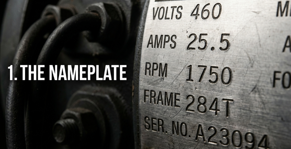
Step 1: Read the Motor Nameplate
Start by recording the motor’s rated voltage, full-load amperage (FLA), frequency, power rating, and service factor. The VFD output voltage must match the motor voltage, while its rated output current must meet or exceed the motor’s FLA.
Service factor shows the motor’s allowable overload capacity. For example, a 1.15 service factor means the motor may operate at up to 115% of its rated load under approved conditions. If the application will use this extra capacity, select a VFD with enough output current and overload margin. Do not size the drive by horsepower or kilowatts alone, because motors with the same power rating can have different FLA values.
Step 2: Classify the Load Type
Variable-torque loads like fans and pumps need lighter overload margins, since torque drops with speed. Constant-torque loads such as conveyors and mixers need heavier overload capacity, often rated for 150 percent of current for 60 seconds.
Step 3: Check the Operating Environment
Ambient temperature, altitude, and enclosure rating all affect how much current a drive can deliver continuously. A drive rated for a clean, air-conditioned panel room will need derating or a better enclosure in a hot or dusty plant. Altitude above 1,000 meters often requires derating too, since thinner air cools the drive less effectively.
Step 4: Plan for Braking and Deceleration
Loads with high inertia, or loads that overhaul the motor during deceleration, push energy back into the drive’s DC bus. Cranes, centrifuges, and downhill conveyors are common examples. Our guide to VFD braking resistors, line reactors, and dynamic braking covers how this energy gets absorbed safely. Otherwise, bus voltage can spike.
How Do Steps 5 Through 7 Protect the Installation and the Network?
Step 5: Confirm Cable Length and Motor Compatibility
Long motor cable runs create reflected-wave voltage spikes at the motor terminals, which standard motor insulation may not tolerate. Inverter-duty motors, output reactors, or a lower carrier frequency setting all help manage this on longer runs.
Step 6: Match Input and Output Specifications
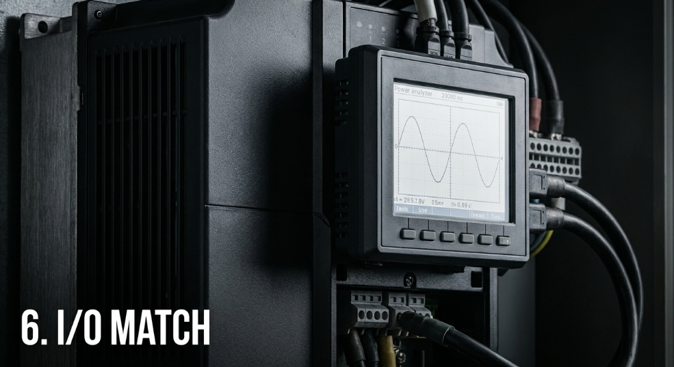
How to choose variable frequency drives at this stage means lining up the input voltage class, output frequency range, and power rating. All three must match the site’s actual grid and process needs. Variable frequency drive specification sheets list these figures alongside overload ratings and communication options, and each one matters for a correct fit.
Step 7: Confirm the Communication Interface
A drive must support the plant’s protocol, such as Modbus, Profibus, Profinet, or EtherCAT. Incompatible communication may require gateways, rewiring, software changes, and commissioning time.
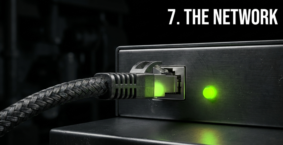
Before ordering, confirm compatibility with the PLC and SCADA system. Check protocol version, communication speed, addressing method, network topology, and required cables.
Verify whether the drive includes the needed port or requires an optional communication card. Review data points, including speed commands, operating status, alarms, current, voltage, frequency, and energy use.
Confirm that compatible GSD, EDS, or ESI files are available for PLC configuration. Also define the drive’s response to network loss, such as safely stopping or running at a preset speed.
See our vector versus scalar control comparison for a guide to selection details.
Why Do Professional Buyers Use This Framework When Purchasing MINGCH Inverters?
MINGCH Electrical publishes full variable frequency drive selection data for its MC3000 and MC9001 series. This includes input and output ranges, overload ratings, and communication options. Both series carry CE-LVD certification and are built in an ISO9001 factory. An in-house R&D team is available for custom braking, cabling, or protocol requirements.
Buyers working through this seven-step method can explore the entire VFD range to compare specification sheets side by side. You can also download the product catalog for complete input, output, and communication details before placing an order.

Frequently Asked Questions
Can a VFD Be Larger Than the Motor?
Yes, but the drive’s motor protection settings must be programmed using the motor’s actual full-load amperage. Oversizing may be necessary for high starting torque, frequent acceleration, high ambient temperature, or altitude derating. Excessive oversizing can increase cost without improving performance.
When Does a VFD Need a Braking Resistor or Reactor?
A braking resistor may be needed when a high-inertia load must stop quickly or when the load drives the motor during deceleration. Line and output reactors may be required for unstable power supplies, long motor cables, or applications needing reduced electrical stress.
How Do I Confirm PLC and VFD Compatibility?
Check the required protocol, communication port, baud rate, addressing method, and network configuration files. Also verify that the PLC can access the needed commands and data, including speed reference, operating status, current, frequency, alarms, and fault history.


