




Power behaves very differently in series and parallel circuits, and this difference directly affects how industrial equipment performs and survives.
In short, series circuits limit total power as loads increase, while parallel circuits allow power to scale with demand.
This article explains how power is distributed, how calculations work, and why industrial equipment almost always uses parallel layouts.
You will also learn how power parallel vs series design principles apply to voltage regulators, transformers, VFD systems, and large factory installations.
Series vs Parallel Circuits: The Core Difference
| Feature | Series Circuit | Parallel Circuit |
| Current path | Electric current flows through a single path | Electric current flows through multiple paths |
| Component connection | Components are connected one after another | Components are connected across the same voltage points |
| Voltage behavior | Supply voltage is divided across components | Each component receives the full supply voltage |
| Current behavior | The same current flows through all components | Current splits between different branches |
| Response to failure | One failure stops the entire circuit | Other branches continue working |
| Typical use case | Simple or low-power circuits | Industrial and building power systems |
How Series Circuits Work
In a series circuit, all components share the same current. The voltage from the power source is divided across each component.
If one component fails, the circuit opens. All connected equipment stops working.
This behavior is similar to older holiday light strings. When one bulb fails, the entire string turns off.
Because of this limitation, series circuits are rarely used for industrial power delivery.
How Parallel Circuits Work
In a parallel circuit, each component is connected directly to the power source. All loads receive the same voltage.
The total current from the source splits between different branches. Each branch draws only the current it needs.
If one component fails, the others continue operating. This independence makes parallel layouts more practical for real-world systems.
This is the same principle used in residential and industrial power distribution.
Understanding Power in Electrical Circuits
Power describes how fast electrical energy is used or converted. It is measured in watts (W).
The basic formula is:
P = V × I
Where:
- P is power
- V is voltage
- I is current
How total power is calculated depends on whether the circuit is series or parallel.
Voltage behavior is also influenced by how power systems manage fluctuations under load, which is explained in more detail in this guide on voltage control in industrial power systems.
Power Calculation in Series Circuits

In series circuits, total power equals the sum of the power used by each component.
It can also be calculated using total voltage and total current.
Key formulas include:
- Total resistance:
Rₜ = R₁ + R₂ + R₃ + … - Total current:
Iₜ = Vₜ / Rₜ - Total power:
Pₜ = Vₜ × Iₜ
Example: How to Calculate Total Power in a Parallel Circuit
Consider three resistors—10 Ω, 20 Ω, and 30 Ω—connected in series to a 120 V source.
First, calculate total resistance:
Rₜ = 10 + 20 + 30 = 60 Ω
Next, calculate the total current:
Iₜ = 120 V / 60 Ω = 2 A
Finally, calculate total power:
Pₜ = 120 V × 2 A = 240 W
As more loads are added, current decreases, which limits total power.
Power Calculation in Parallel Circuits

In parallel circuits, total power is also the sum of the power used by each branch. The difference lies in how resistance and current behave.
Key formulas include:
- Total resistance:
1 / Rₜ = 1 / R₁ + 1 / R₂ + 1 / R₃ + … - Total current:
Iₜ = I₁ + I₂ + I₃ + … - Total power:
Pₜ = Vₜ × Iₜ
This difference explains why power in series and parallel circuits behaves so differently in system design.
Example: How to Find Total Power in a Parallel Circuit
Using the same resistors—10 Ω, 20 Ω, and 30 Ω—connected in parallel to a 120 V source:
Branch currents:
- I₁ = 120 V / 10 Ω = 12 A
- I₂ = 120 V / 20 Ω = 6 A
- I₃ = 120 V / 30 Ω = 4 A
Branch power:
- P₁ = 120 V × 12 A = 1440 W
- P₂ = 120 V × 6 A = 720 W
- P₃ = 120 V × 4 A = 480 W
Total power:
Pₜ = 1440 + 720 + 480 = 2640 W
The total power is much higher because parallel circuits reduce total resistance and allow more current to flow.
Why Parallel Systems Dominate Industrial Applications
Industrial power systems are built for high loads, long operating hours, and steady expansion over time.
This comparison between power parallel vs series explains why industrial systems favor designs that scale without limiting available power.
Parallel circuit design fits these conditions better than series layouts in real factory environments.
Rather than pushing all power through a single electrical path, parallel systems divide the load. This approach gives engineers more control and makes planning for growth easier.
Improving System Availability with Parallel Design

One major advantage of parallel circuits is independent operation between components. If one unit stops working, the rest of the system keeps running.
In industrial settings, this difference matters. Unexpected downtime often leads to production delays and missed output targets.
A common example involves large motors driven by multiple VFDs connected in parallel. When one drive needs service, the motor can continue running at reduced output.
Hot-swappable UPS systems follow the same idea. Power stays available while maintenance is carried out.
Supporting Growth Through Modular Expansion
Parallel systems also support expansion without disruption. New equipment can be added while existing units remain in service.
Many facilities choose several smaller transformers instead of one oversized unit. Connecting them in parallel spreads the load and simplifies future planning.
This method allows gradual investment rather than large upfront spending. As demand increases, capacity can grow step by step.
Case Study: 3000 kVA Parallel System in an Industrial Facility
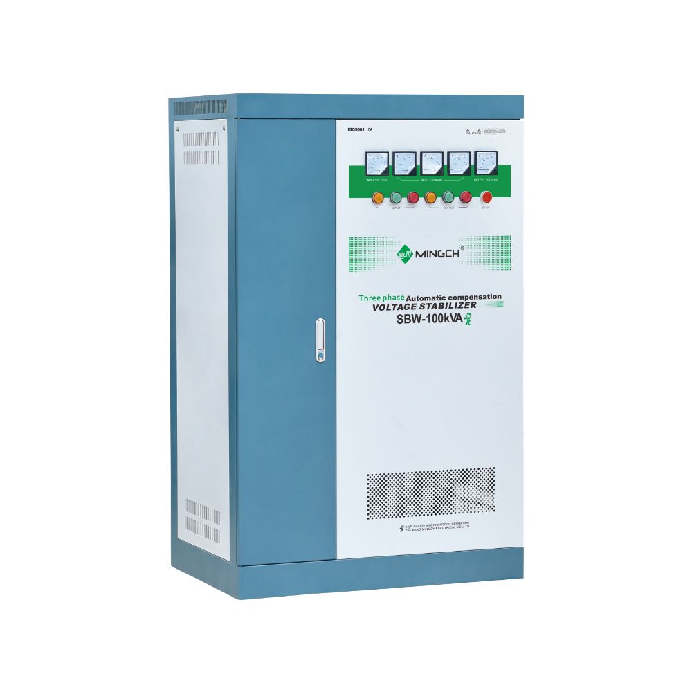
A large manufacturing plant experienced frequent equipment issues due to unstable incoming power. A common solution in such cases is installing multiple high-capacity voltage stabilizers operating in parallel.
The combined system capacity reached 3000 kVA. All major production lines were supplied through this parallel structure.
Maintenance could be performed on individual stabilizers without shutting down the factory.
As a result, equipment maintenance time dropped by 40 percent.
Overall operational efficiency improved, showing the real-world value of parallel power design.
Conclusion
Discover MINGCH Manufacturing Excellence
Step inside our factory to see how high-quality voltage regulators and inverters are engineered for precision and durability.
Explore Our FactoryPower behavior shapes how industrial systems perform and scale. Series layouts limit growth. Parallel layouts support expansion, maintenance, and stable operation.
If you are planning a project, prepare your load list or single-line diagram. The engineering team at MINGCH Electrical can review it and design a one-stop solution directly from the factory.
Frequently Asked Questions
What is the total power in a parallel circuit?
It is the sum of power used by each branch. Power increases as loads are added.
Why are series circuits rare in factories?
They limit voltage and power. One failure affects all equipment.
Are parallel systems easier to expand?
Yes. New loads can be added without changing existing branches.
How do engineers size parallel systems?
They calculate the total current and include safety margins.


